Brief theory
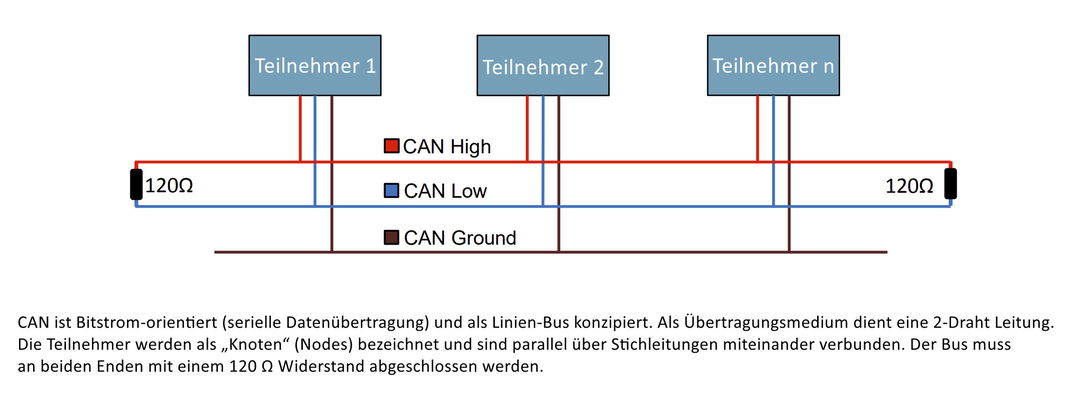
Communication between the individual "intelligent" components of the Stromer takes place via a 2-wire bus. Stromer uses the CAN bus. CAN stands for Controller Area Network. This serial bus system was developed by BOSCH in 1986 specifically for use in cars. It is defined as a communication standard according to ISO 11898-1 and layer 2 (data security layer) in the ISO/OSI reference model. There are a whole host of protocols for this (ISO-TP / CANopen / J1939 etc.)
Nodes are connected to the serial bus, which can place messages on the bus and retrieve messages from the bus. A CAN controller manages the underlying environment, e.g. the CAN controller of the battery manages the battery.

The CAN bus history in short
- Pre CAN: Car ECUs relied on complex point-to-point wiring
- 1986: Bosch developed the CAN protocol as a solution
- 1991: Bosch published CAN 2.0 (CAN 2.0A: 11 bit, 2.0B: 29 bit)
- 1993: CAN is adopted as international standard (ISO 11898)
- 2003: ISO 11898 becomes a standard series
- 2012: Bosch released the CAN FD 1.0 (flexible data rate)
- 2015: The CAN FD protocol is standardized (ISO 11898-1)
- 2016: The physical CAN layer for data-rates up to 5 Mbit/s standardized in ISO 11898-2 (in practice up to 8 Mbit/s)
- 2018: CiA starts development of CAN XL
- 2024: CAN XL standardized (ISO 11898-1:2024, 11898-2:2024)
If you want to read up a little, you can do so at here do.
Components with CAN interface
Components of a Stromer with CAN interface are
- the controller (MCU)
- the battery and the charger
- the Supernova m99 Pro front light (ST2S, ST5)
- the ABS from Blubrake
- the OMNI, the Stromer's control center
Diagnosis
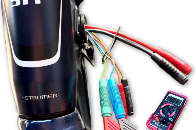
You can use a multimeter to measure whether the CAN bus in the Stromer has a fundamental error. To do this, connect an appropriately adapted Wicket Cable to the charging connection and measures:
- Set the multimeter to resistance mode [Ω] and connect the test leads to the CAN-High or CAN-Low line. The measured resistance should be in the range of 60-70 Ω.
- Set the multimeter to direct voltage measurement mode (DC) [V] and connect the test leads to the CAN high or CAN low line and ground. The measured voltage should be around 2.5 volts on both lines. For CAN-H it is approx. 2.4 volts, for CAN-L approx. 2.6 volts. Voltage differences outside this range may indicate a possible problem.
The determination of a correct Ω value or voltage value does not mean that the software communication is correct. To do this, you would need to connect a data logger and ultimately know how to interpret the data. For measurements on the CAN bus this reading recommended.

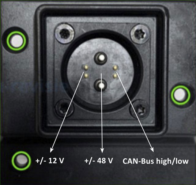
Rosenberger connection:
