
ST5 2021 ABS | ST5 2018
ST3 2022 Pinion | ST3 2018
ST2 2020 Belt
ST1 2021 LCI | ST1 2019
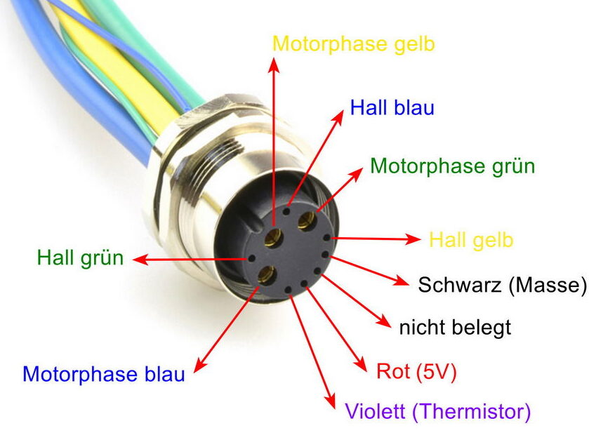
From 2019 onwards, new wiring was used. An „all-in-one“ Higo connector is used. Type HG-F.M-L1019A, which unites all connections from and to the engine.
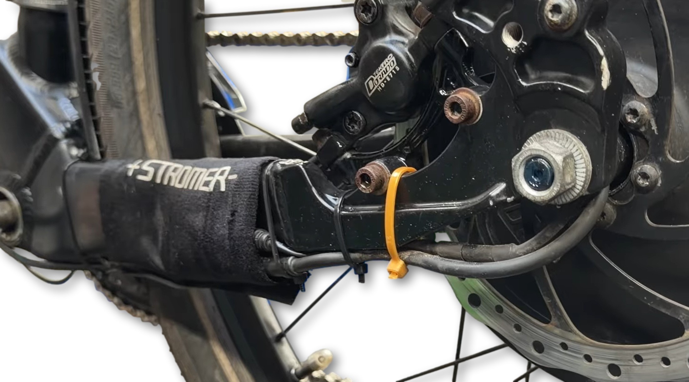
Shown here is the cable socket Higo Panel Mount L1019AM 03 DQ 300 on the left chain stay.
ST1 / V1
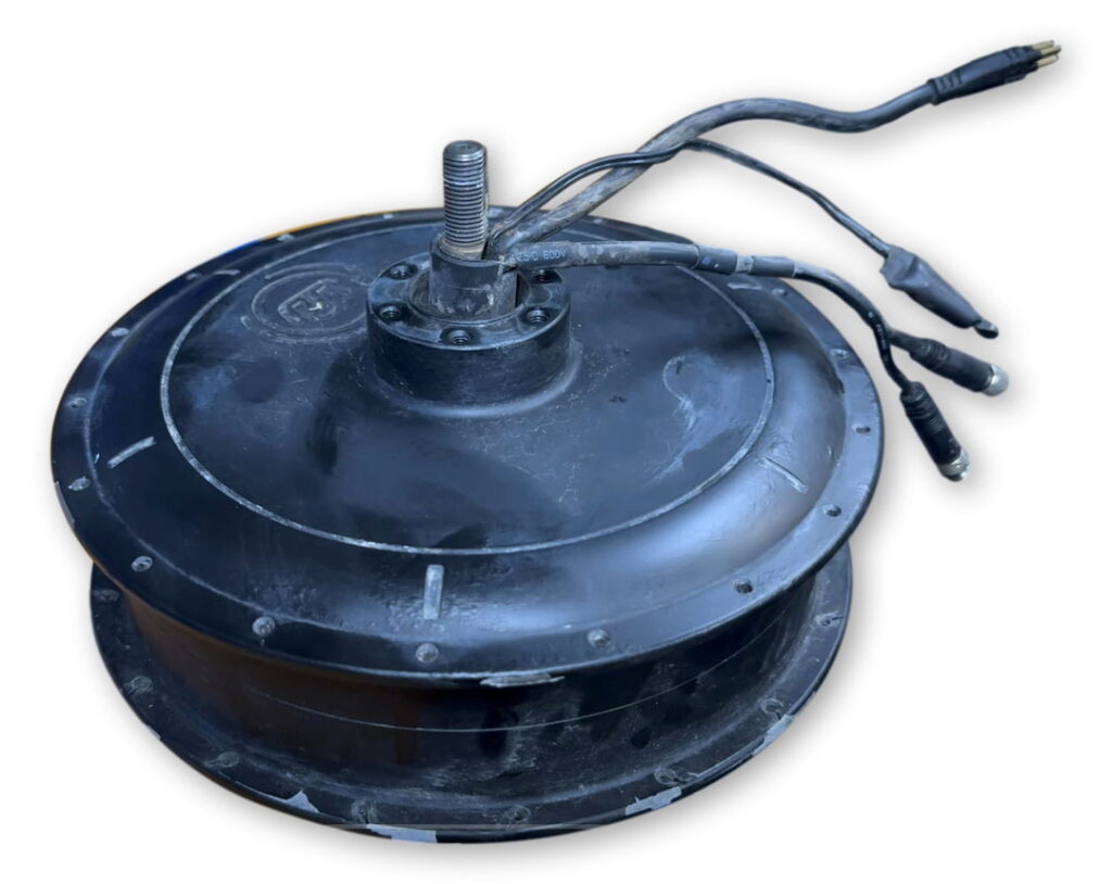
Stromer used various motors from different manufacturers in the course of model development. Accordingly, different connection configurations were also used.
Pin assignments
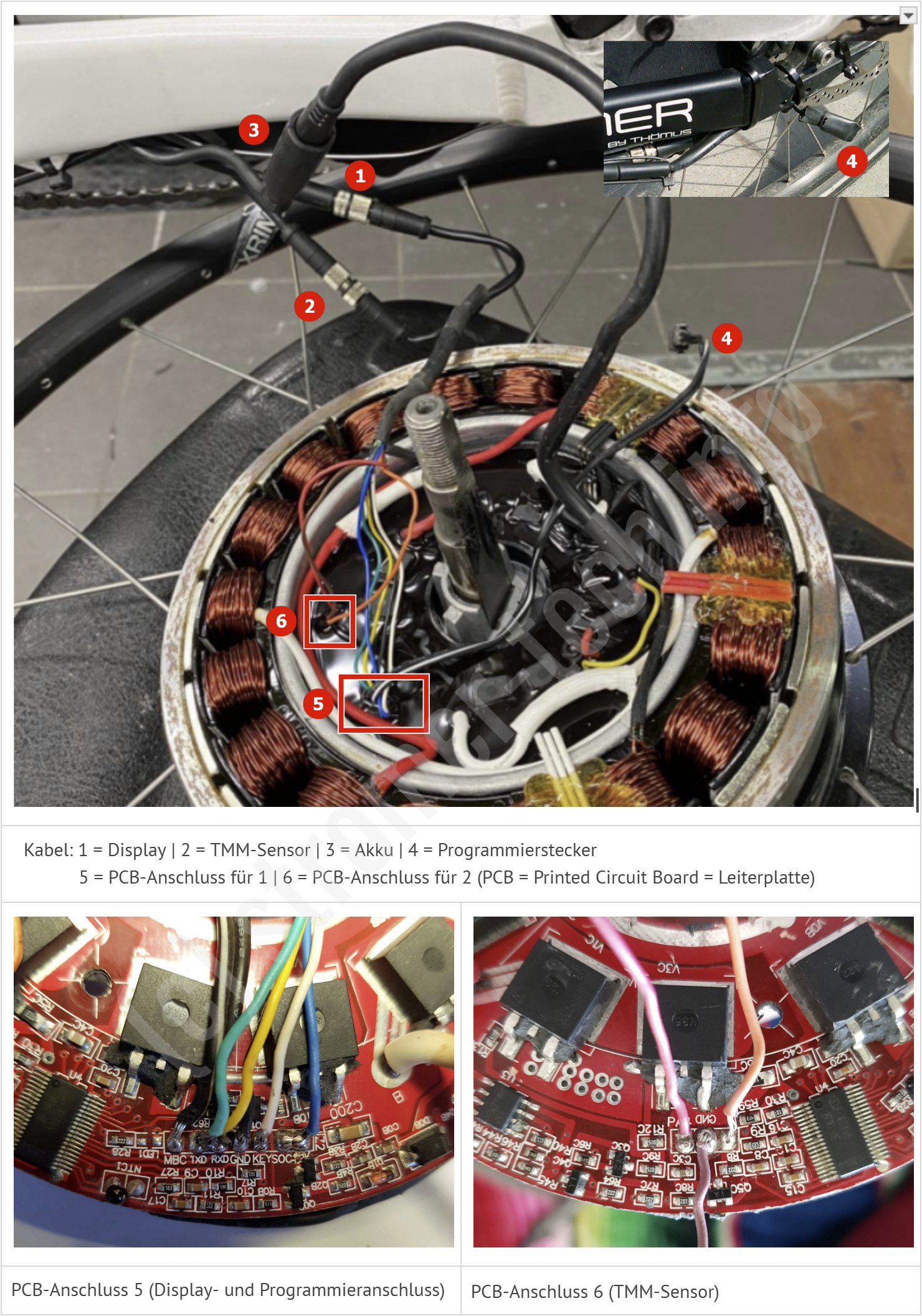
- Display (Source)
The display communicates with the motor controller via a serial interface. The wire color refers to the original wiring harness extending upwards from the controller. Pin assignment on the display side:
- Pin 1 (Pink) Display) or. Black on the PCB:
Ground(Mass) - Pin 2 (Yellow):
Texas(UART send data from controller to display).
If interruptedNO_COM/ICURR - Pin 3 (Blue):
Power in(Battery voltage / Vbatt, approx. 36V–42V)
If interruptedNO_BATT - Pin 4 (White):
POW_OUTSwitched Plus - Input from the display; signals to the controller that the display is switched on/unlocked - Pin 5 (Green):
Prescription(UART reception data from display to controller).
If interruptedNO_COM/ICURR
- Pin 1 (Pink) Display) or. Black on the PCB:
- TMM sensor
Der TMM-Sensor im linken Ausfallende misst die Kettenzugkraft und liefert ein analoges Signal an den Controller. Misst man den Widerstand Richtung Controller gegeneinander, liegen die Werte meist bei ca. 2 bis 3 Ohm.
- Red
+5VSupply voltage for the Hall sensor in the TMM sensor - Brown
Ground(Mass) - Orange
Signal(Analog output signal from the TMM sensor to the controller, usually a voltage value between 0.5V and 2.0V, depending on the pedal pressure)
- Red
- Battery (+/− 36 V & SoC)
- Rot (+ 36 V)
- Black (-36 V)
- Yellow (SoC = State of Charge = Battery charge level)
- Controller programming port
Auf der Platine des TDCM/ASI-Controllers existiert eine zusätzliche Schnittstelle die als Kabel mit einem JST-Stecker aus dem Motor geführt wird. Dieser Stecker wird genutzt, um den Infineon-Prozessor in den Bootloader-/Flash-Modus zu versetzen (z. B. für Firmware-Updates via Infineon Memtool).
- MBC (Monitor Board Communication / Boot): This is the data or programming line (often coupled with the reset/boot pin of the microcontroller).
- GND The associated signal ground.
⚠️ Important information about flashing: If the two pinsMBCandGroundwith each other short-circuited werden und danach das System eingeschaltet wird, erzwingt dies den Flash-Modus des Prozessors. Für die eigentliche Datenübertragung beim Programmieren wird dann die serielle Schnittstelle des Displays (Grün/Gelb/Schwarz) an einen USB-zu-RS232-TTL-Konverter angeschlossen, üblicherweise mit einer Baudrate von 57600.
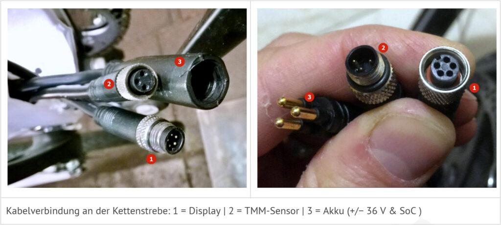
ST2 before 2018
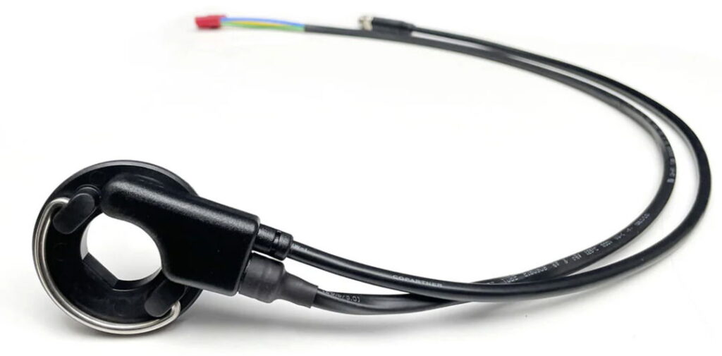
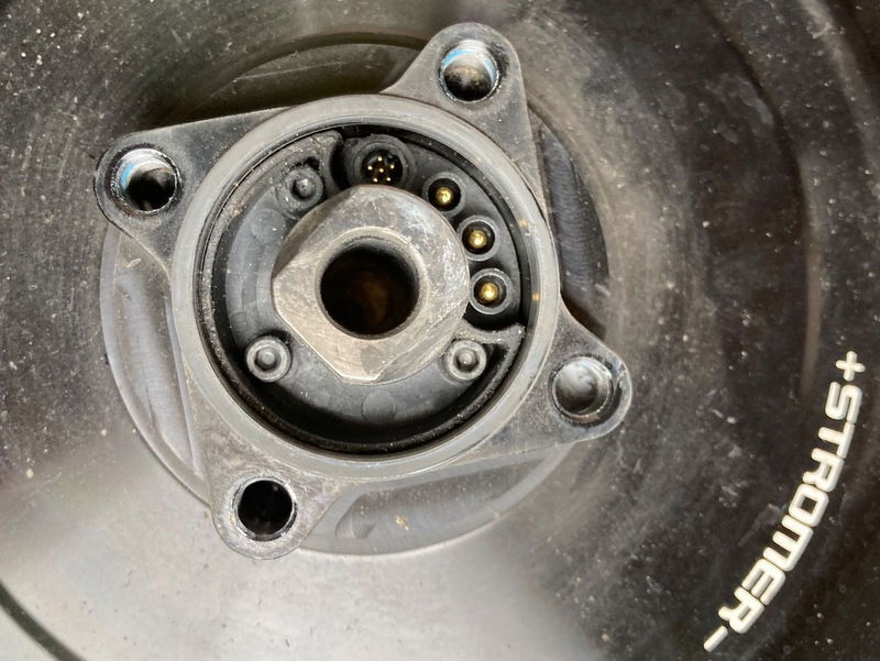
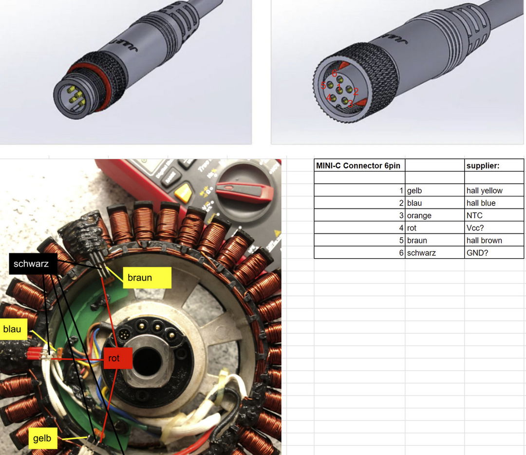
For the sensor cables, a connector from HT-F-M Mini C Used mutually.
Related articles
- OMNI - DISPLAY V1 / V1.1 - Display V1 / V1.1 > Pin assignment'
- ELECTRICS & ELECTRONICS - 'Check wiring'
- PROBLEMS - MOTOR - 'Repairs'
- PROBLEMS - MOTOR - 'Hall or temperature sensor defective'
- PROBLEMS - ERROR MESSAGES / WARNINGS - 'E210207 | Moisture in the motor connector'