ST3 / ST5
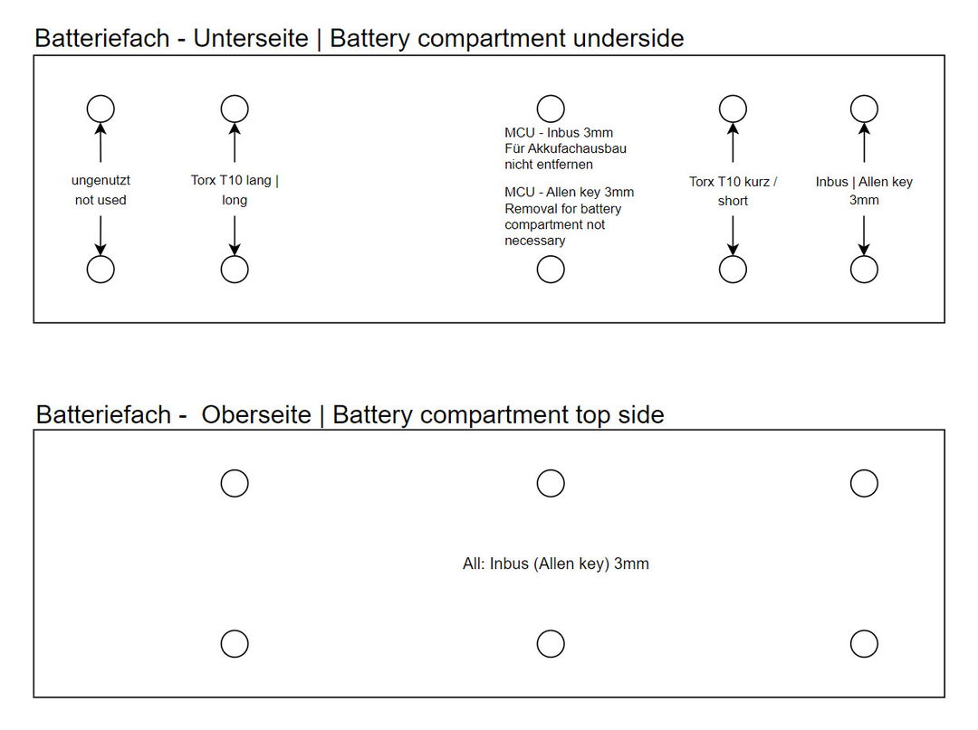
Removing the battery compartment is a bit of a fiddle. The Screw plan The screws shown must be removed. Once the screws have been removed, you can try to pull the compartment out of the frame at the top left. You can use a thin spatula to help prevent the compartment from sticking to the frame. Once the compartment has been pulled out a little at the top left, it can be released from the frame at the bottom of the loading lid and then extended upwards with small rocking movements.

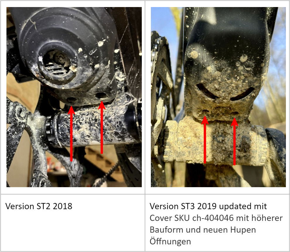
To be able to remove the controller from under the down tube, the two 3 mm Allen screws marked MCU must also be removed. The down tube cover with its two Allen screws underneath the horn must also be loosened.

ST1 / ST2 Belt / ST7
On some Stromer models, the controller and the distribution board are integrated in the battery compartment. On the ST1 / ST2-Belt, for example, the charging flap can be removed via a 4 mm Allen screw at the bottom of the down tube. To access the controller/distribution board, it is sufficient to remove the 4 screws in the compartment.