how individual Stromer components and assemblies can be tested with the System Integration Test (SIT) here.
In addition to the components, their wiring can also be a source of errors. The following problems can occur:
- Corroded or loose plug connections
- Crushed, torn or chafed cables
- Unplugged connectors
Due to the predominantly in-frame cabling used at Stromer, inspection is not always easy. Below, I have compiled a list showing possible sources of error related to the wiring.
TMM-Sensor → Connector / Cable
Older models had a continuous cable from the sensor to the Omni. Newer models use a plug-in connection in the right-hand chain stay.
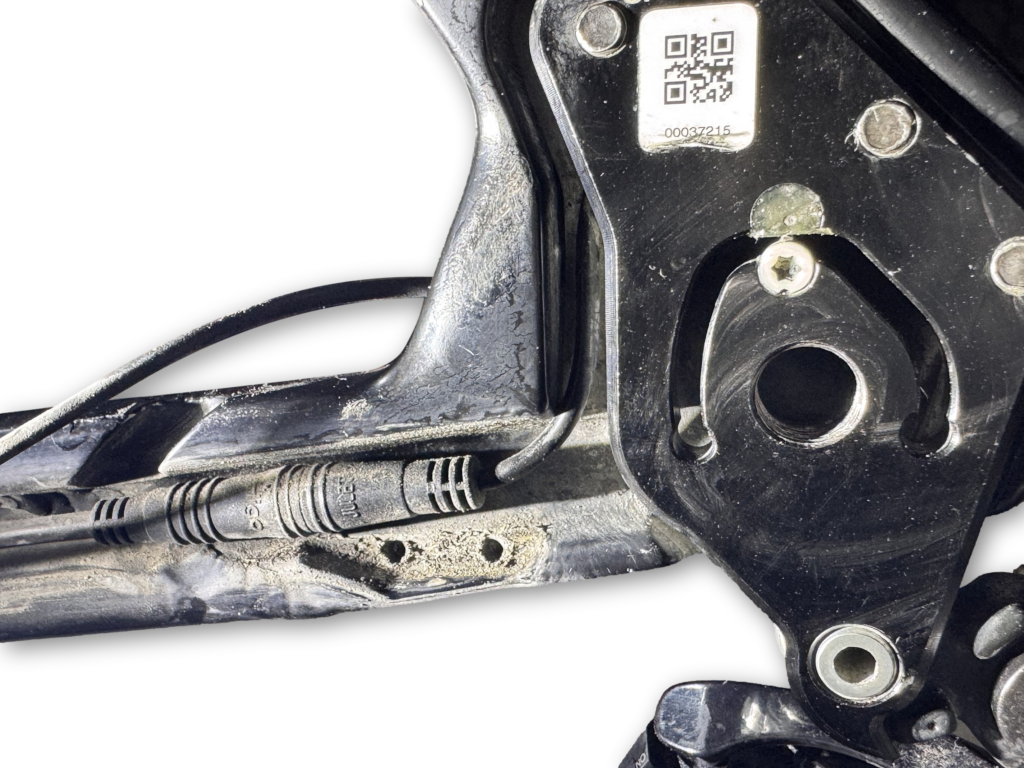
There are problems with support, the TMM sensor is often targeted. Although it is not the primary source of errors, checking the wiring is worthwhile.
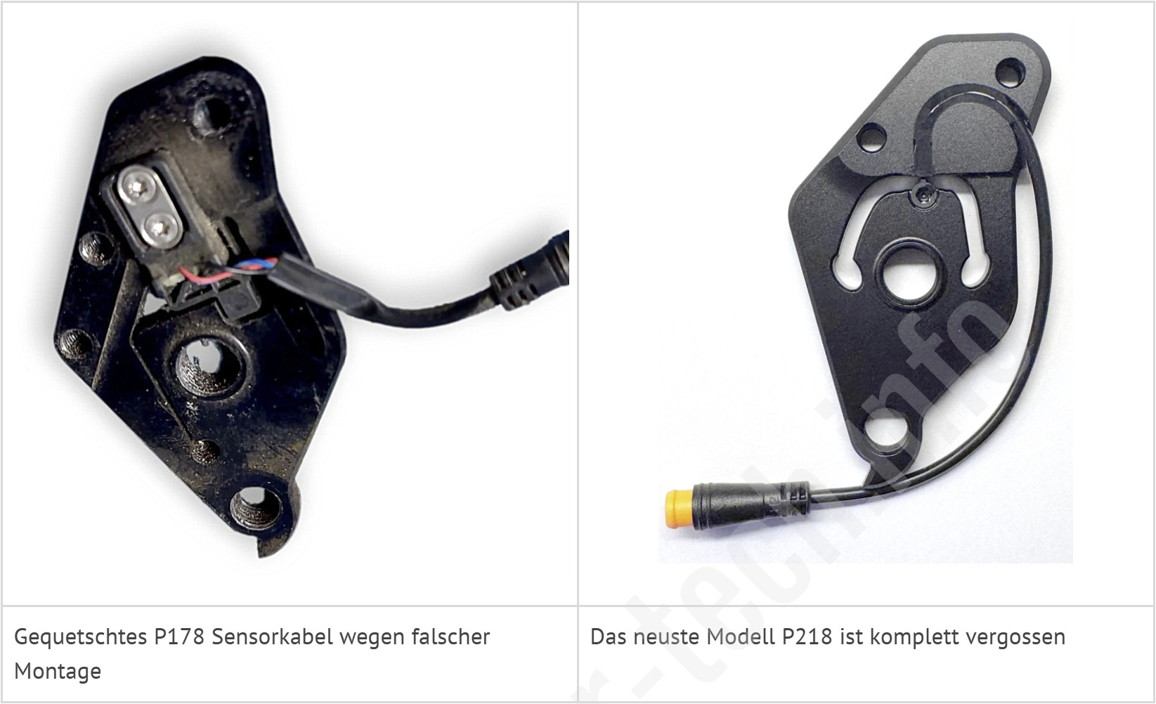
In this P178, the cable was pinched due to incorrect installation. Newer TMM sensors (P211/P218have been shed, and the problem no longer arises.
Motor cable on the left chain stay
In older models, three wires led to the motor (motor cable, as well as Hall and temperature sensor), with the Hall and temperature sensors merging into one again shortly before the motor. There was also a programming port for hub motors with integrated controllers.
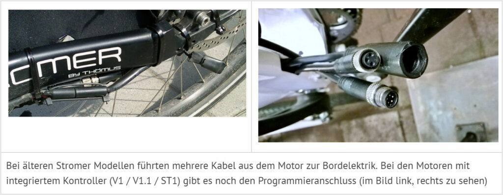
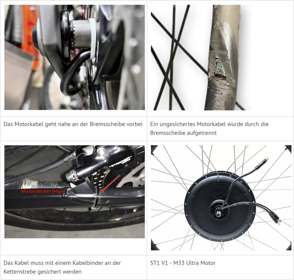
In newer models, the wiring was simplified to a Higo screw connector, which includes all connections to the motor (3-phase motor cable, Hall, and temperature sensors). The cable runs close to the brake disc and needs to be secured in position with a cable tie.
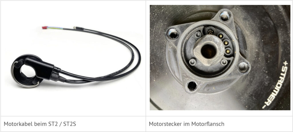
On the ST2 (2016) / ST2S, the motor connector is installed directly on the motor flange. With this type, it is cable breaks or mechanical problems that lead to faults in the support. A repair is difficult, usually the cable has to be replaced.
Motor cable in the pedal bearing area
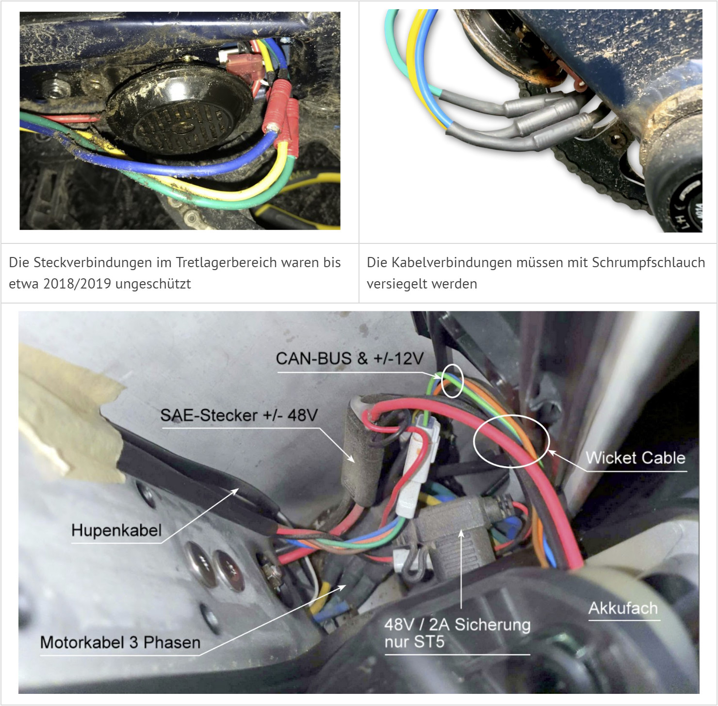
In models with the controller under the downtube, the three motor phase cables run through the bottom bracket area to the motor. The ST2 platform models (ST1x / ST2 / ST2S) were affected by a „design flaw“: the motor cable connectors to the controller were not sealed. In 2018, Stromer issued a TSB (Technical Service Bulletin / Work instruction) have been issued for these models, which describe how the engine cables can be subsequently sealed.
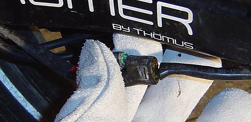
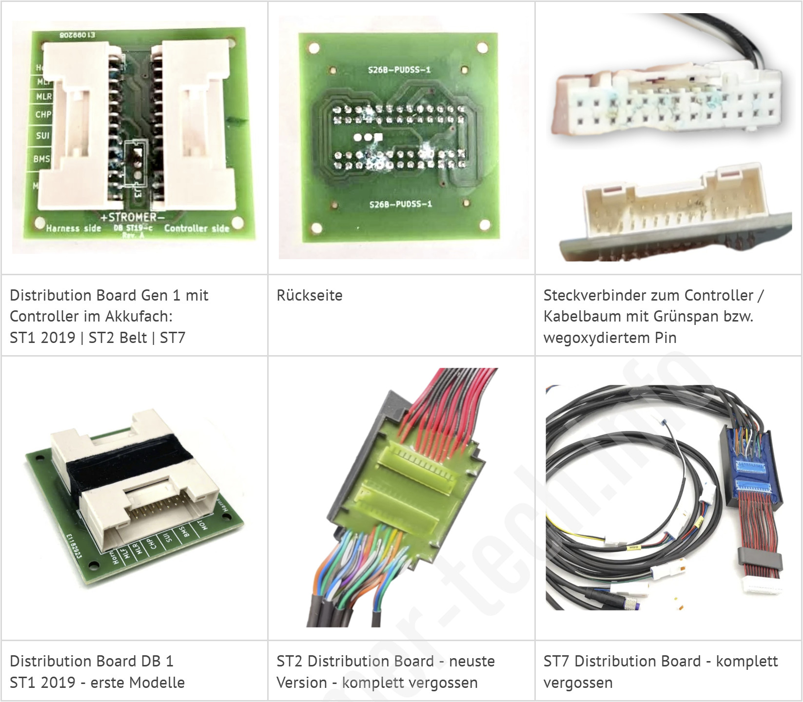
On the old ST1 V1/V1.1, the motor cables ran over the left-hand chain stay. Moisture in combination with current flow sometimes led to corrosion at the plug connections, which can be clearly seen in the blue/green deposits known as verdigris.
Wicket Cable
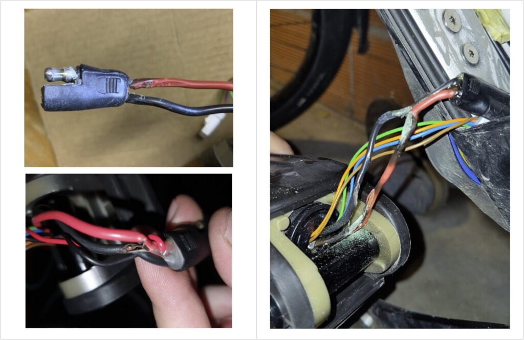
The Wicket Cable connects the battery output to the controller and is located in the battery compartment/bottom bracket area. It connects the onboard voltage (48 V or 36 V), the auxiliary voltage 12 V (or 6 V) for the Omni, and the CAN bus connection of the battery to the onboard electronics. Due to overloading of the 48 V circuit and, in some cases, moisture in the bottom bracket area, the connector (SAE plug) can corrode, subsequently burn through, and/or cause short circuits.
Distribution Board (ST1, ST2-Belt, ST7)
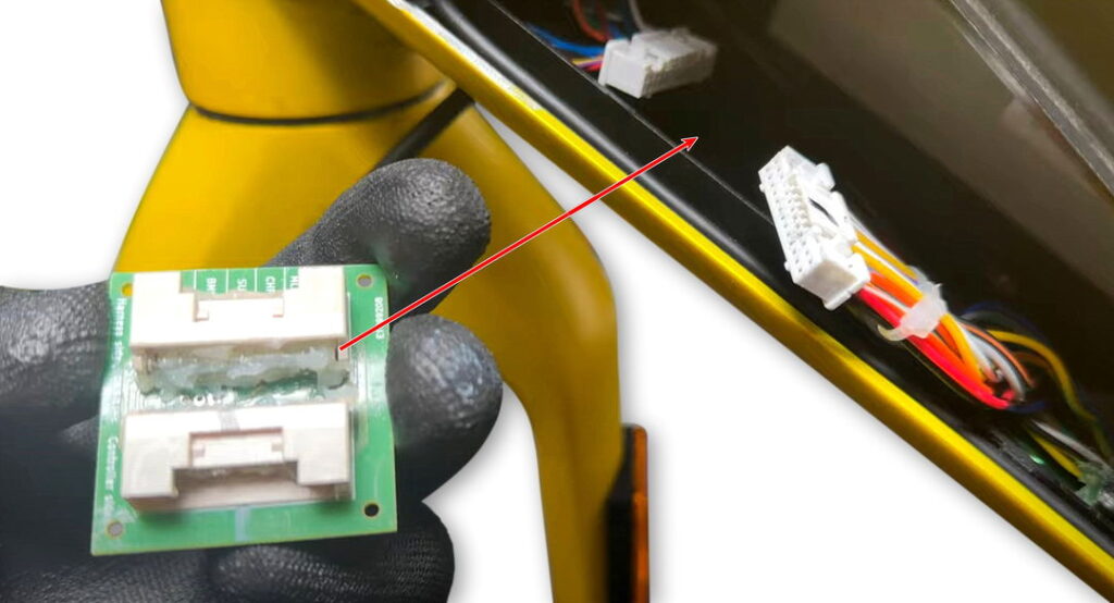
The ST1, ST2-Belt, and ST7 models have the controller integrated into the downtube. The connection to the bicycle's electrical system is made via a distribution board. Moisture (condensation) in the battery compartment can lead to corrosion of the distribution board, resulting in malfunctions.
Distribution Board ST5 (early model years), ST2, ST2S, ST1x
The first batches of the ST5 had a distribution board in the stem. Moisture and infiltrated water led to corrosion and contact problems, resulting in corresponding errors. The ST1x, ST2, and ST2S, which had the distribution board mounted in the battery compartment at the top, experienced the same problem.
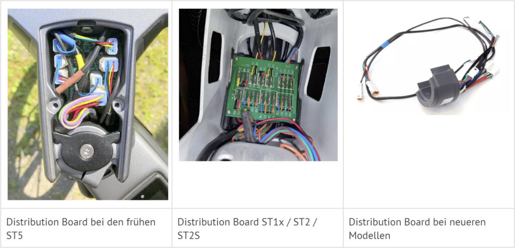
Stromer is offering an upgrade for the ST5 where the distribution board in the stem is removed and replaced with new wiring.
Battery socket, charging socket, battery compartment socket
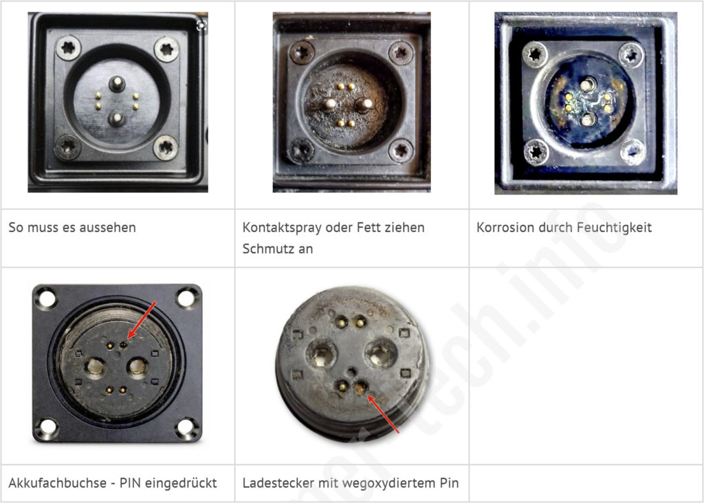
Stromer uses the magnetic Rosenberger connector for detachable connections. Detachable connections include the charger plug, the charging socket in the Stromer, the battery base, and the Rosenberger socket at the very bottom of the battery compartment. The Rosenberger connector is practical and, due to its magnetic properties, remains securely connected even while riding. However, it is prone to corrosion when exposed to moisture in combination with electrical current. Furthermore, its magnetic property attracts tiny metal particles, which can lead to leakage currents or short circuits. The spring-loaded pins in the battery compartment socket and in the charging plug can also be a source of malfunction.
Brake lever contacts
The brake levers have a built-in reed switch that controls the brake light and triggers recuperation. The right brake lever is also needed for accessing the service menu. On models with Magura brakes, the brake cables between the brake lever and the frame have a plug connector.
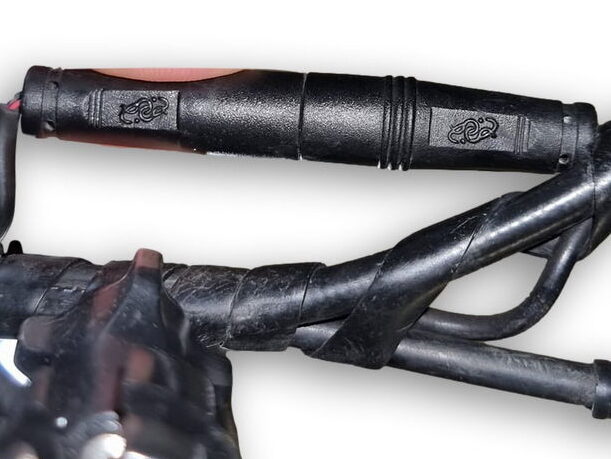
Problems with the reed switches are rare, but the plug connection on the Magura brakes is a source of faults.
Torn cables
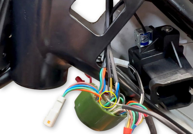
The wiring of the electric motor is housed within the frame, where it can be very cramped in places. The rotating movement of the handlebars, in particular, puts mechanical stress on the wiring. This type of fault is rare, but it can happen that a cable tears or gets crushed due to incorrect assembly.
Omni connection board
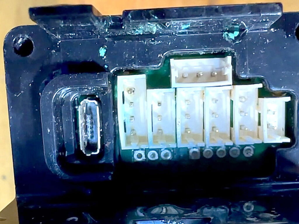
All information comes together in the Omni, as do all the cables from the peripheral devices.
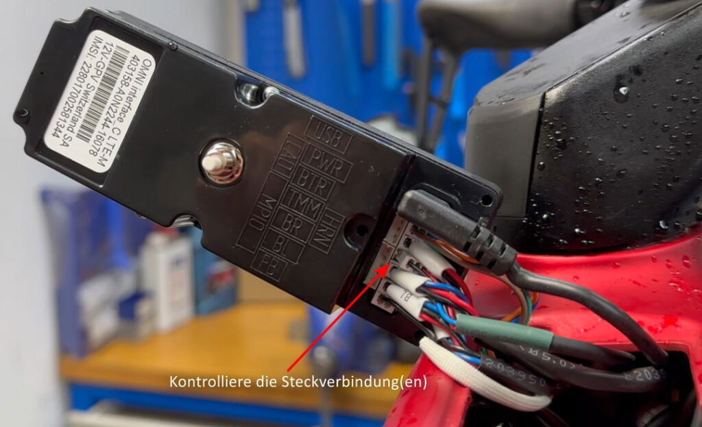
In this example, there were problems with the TMM sensor. The cause was a disconnected TMM sensor cable. During assembly, care must be taken to ensure that the connectors snap securely into the connector housing.
Besides loose connectors, the Omni, like other connectors, has the problem of corrosion. The typical appearance of corroded connectors is green-blue deposits – so-called verdigris. It is caused by moisture in combination with current flow and leads to contact problems and malfunctions.
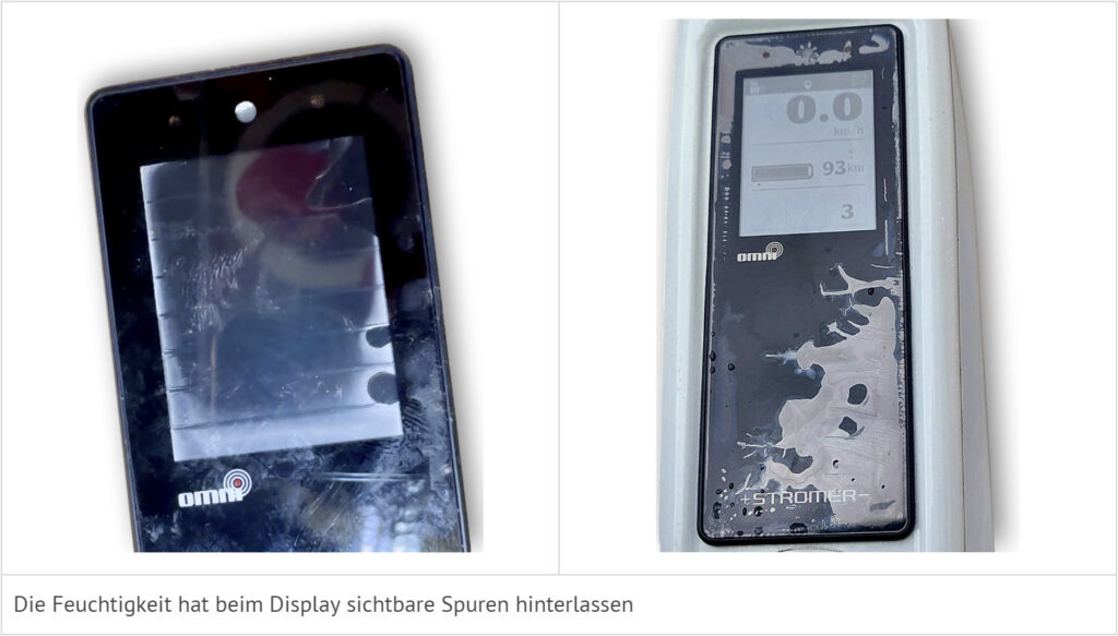
Omni Display - Water
The Omni Display can also be damaged by water ingress. It cannot be repaired. The entire Omni must be replaced.